Die Cast Tooling Reverse Engineering Experts
Advanced Reverse Engineering Technology at PHB Corporation
Need to Create a 3d Model and Tooling from an Existing Die Cast Part? We Can Help.
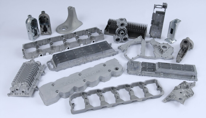
For over 100 years, PHB Corporation has been a full-service supplier of quality products using our extensive capabilities in aluminum and zinc die casting. On top of our turnkey service that includes new die cast tooling design, we also offer reverse engineering of Aluminum, Zinc, Plastic, and Rubber injection molds. We can quickly create 3D models of your part and create new tooling or a tooling rebuild to get you back in production. Beyond producing or rebuilding dies, we also welcome to opportunity to be your turnkey solution, from designing and building molds, to providing production runs with our extensive pressure die casting and CNC machining capabilities.
Why is diecast tooling reverse engineering technology beneficial?
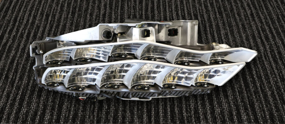
From time to time customers need to move existing die casting programs. When this happens it isn’t always possible to have the original design drawings that were used to build the die cast tooling or the 3D models may not exist. Our reverse engineering capabilities can take the frustration out of repairing existing tooling and even replacing the die inserts without replacing the entire die. An accurate die rebuild can be completed using only an existing injection molded or die cast part.
PHB’s diecast reverse engineering capabilities
Our innovative 3-step reverse engineering process focuses on accuracy, efficiency, and time savings. While other companies often rely on third party supply chain resources, PHB has the resources internally to create highly precise reverse engineered 3D models and drawings.
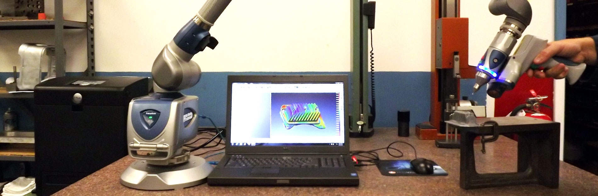
- Step 1: SCANNING PHASE: The process begins with the Scanning phase. PHB uses a FARO Design ScanArm to laser-scan the tooling, accurately capturing all the fine details. The information is gathered through the scan using PolyWorks, a Universal 3D Metrology Software platform, which is capable of producing raw digitized point cloud models. In PolyWorks Inspector, engineers are able to review and generate a report of dimensions, used later in the solid model creation stage.
- Step 2: REPAIR PHASE: In the repair phase, the raw digitized point cloud model is converted into a polygonal model, a process called meshing. The raw mesh data is cleaned up and repaired using tools in the software package. The PolyWorks Modeler program can also create new features or make any necessary changes.
- Step 3: MODEL PHASE: In the third and final model phase, a fully featured parametric solid model is created using Creo Parametric Modeling Software. This process produces a fully editable feature based model when left in native Creo format or can be exported as surface model for use in any CAE, CAD and CAM software.
PHB uses this three-phase reverse engineering process to help customers quickly design, repair, and create solid models ready for production. Cutting edge technology like PolyWorks Modeler Package and Creo Parametric Modeling Software helps PHB lead the way in reverse engineering technology.
If you have a program with tooling that is at the end of its usable life and needs to be moved, repaired or replaced, contact PHB today.